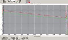
They say a picture is worth a thousand words, and the OTDR picture, or “trace” as they are called, takes a lot of words to describe all the information in it.
The image to the left illustrates a common distance measurement data of a fiber optic strand. Click on the image to get a bigger version.
The screen shot shows the OTDR setup parameters including things like pulse width, range, wavelength and average points of data acquired. Likewise, data such as the length of fiber optics and 2 point loss (db) is also shown.
Equipment used to acquire trace :
CMA 4000
GN Nettest Networks
infoBit – If the fiber looks nonlinear at either end, especially near a reflective event like a connector, avoid that section when measuring fiber loss.

